Garrattfan's Modelrailroading Pages
OO9 NGG16
Chapter 01 Chassis
October 12, 2008 till October 15, 2008
It took me about a week to get the courage to get started. I spent quite a lot of time doing some research and getting my work organised. But at last I placed my first cut in the brass and set out for a new adventure. Building starts with the foot plate of the front drive unit
First cut (1.1) |
First fold (1.1) |
First soldering (1.2) |
Laundry pegs are used to clamps the parts together (1.6) |
The pilot, cow catcher, and floorplate of the front drive unit. The photographer and the pin are intended to indicate the size. (1.7) |
Using 0,7 mm wire to position the spring overlays. Only the upper wire was soldered, the other two are helpers. Than a helper is replaced by the actual wire and soldered and so the third. The pegs hold things fixed (1.8). Remark: the manual states that 0,7 mm wire is to be used to position the spring etch. DO NOT solder the most forward hole and the corresponding hole on the other frame plate (upper two on this photo). Just make sure it is in position but don't solder it. You'll need these holes to run a full length 0.7 mm wire through the frame to hold the gear box in place!! Only after installing the gear box you can solder these holes and file them down to 0,2 mm. I found this out the hard way |
The frame assy with springs and brake rods (1.9) |
To handle the brass mainframe bearings I put them on a tooth pick. The tapered end gets a gold on them. I applied solder paint and soldered them in the frame (1.10)
|
The bearings were oversized. I used my drill stand, drill and a cutting disk to cut the bearings to size (1.10)
|
This is what the chassis looks like after folding (1.11) |
Test fitting the frame |
Wow. My collegues rumour that I get excited from a naked ...... steam locomotive. I guess they're right ;-) |
Now a major question: are you really an expert?? This not a dril (no I don't mean that thing on the next photo). The question is for real. On the previous photo's, have you seen the beginners error I made? No? Take a good look at the photo's on stage 1.9 and stage 1.11 (all three of them). Once you know it, it's clearly visible. It is as stupid as wearing your shoes on the wrong foot. No clue? Now here's the answer
|
The curling is easily corrected by rolling a files back over it. The rivet valve gear punch (from a Rai-Mo kit) serves as riveteer.
|
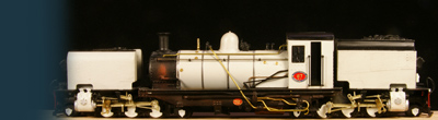
Both frames assembled and temporarily on two wheelsets with the "bridge" between them to indicate the size of the final model. |
With my NS 7000 alongside for comaprison. For a 2 ft gauge loco the NGG16 is surprisingly large!! |


Sign my
GuestBook